Reboot and Shutdown
Important
This feature might not be applicable to all Platforms. Please check individual Platform pages, section Supported Features to confirm if this feature is listed as supported.
Overview of the reboot modes supported
RD-V3 platform supports:
Shutdown: Upon receiving a shutdown request, the application processor (AP) conveys it to the System Control Processor (SCP) through the SCMI communication channel, initiating a dynamic power-down for the AP cores. Subsequently, the SCP executes the shutdown sequence, notifying the Runtime Security Engine (RSE) and then the Manageability Control Processor (MCP). In response to the shutdown request, the RSE undertakes power-down activities and enters the Wait for Interrupt (WFI) mode. Meanwhile, the MCP performs its power-down procedures and communicates with the designated entity responsible for system shutdown (e.g., BMC controller), which is responsible for configuring the Power Management Integrated Circuit (PMIC). On RD-V3 FVP platforms, when the MCP UART print the shutdown message, the FVP platform terminates its operations.
Cold reboot: Upon receiving a cold reboot request, the AP signals it to SCP through the SCMI communication channel, and then initiate the dynamic power-down for the AP cores. Subsequently, the SCP executes the power-down sequence, notify the MCP and then RSE. In response to the cold reboot request, MCP undertakes power-down activities and enter WFI mode. Meanwhile the RSE will perform its power-down activities and issue a system wide reset by programming the system reset register. This will reset the entire system including RSE, SCP, MCP, LCP and AP cores.
Warm reboot: In the warm reboot mode, designed for an Application Processor (AP) exclusive reboot, the AP signals the System Control Processor (SCP) through the SCMI communication channel, initiating a dynamic power-down sequence for the AP cores. Upon receiving the warm reboot request, the SCP places the AP cores in a static power-off mode by programming the Power Processing Units (PPUs). After ensuring that all cores are statically powered down, the SCP proceeds to power up the boot CPU.
Impact of power-down on various components:
RSE |
SCP |
MCP |
LCP |
AP |
|
|---|---|---|---|---|---|
Shutdown |
OFF |
OFF |
OFF |
OFF |
OFF |
Cold reboot |
Reset |
Reset |
Reset |
Reset |
Reset |
Warm reboot |
NILL |
NILL |
NILL |
NILL |
Reset |
Power-down sequence for RD-V3 platform
AP side
The power-down sequence remains consistent for shutdown, cold reboot, and warm reboot at the Application Processor (AP) end.
Upon receiving the power-down request, the Linux kernel performs cleanup activities and utilizes the Symmetric Multiprocessing (SMP) framework to transition all secondary CPUs into Wait for Interrupt (WFI) mode. The primary CPU leverages the EFI reboot runtime service to initiate a PSCI call with the power-down mode, resulting in a context switch on the AP side. CPU0 transitions from non-secure world to root world.
Subsequent to the switch to secure mode, CPU0 generates a Software Generated Interrupt (SGI) to bring the secondary CPUs into secure mode, triggering the execution of the ISR for the SGI. Within the ISR, secondary CPUs execute the power-down sequence, including disabling further interrupts and entering dynamic power-off.
Concurrently, while secondary cores are executing the ISR, the primary CPU dispatches an SCMI message to the System Control Processor (SCP), undertakes power-down activities, and enters dynamic power-off.
The distinction between shutdown, cold reboot and warm reboot occurs at the SCP.
Shutdown
The SCP manages a power tree for the RD-V3 platform, with SysTop power domain at the apex, followed by cluster power domains and CPU power domains at the lower levels.
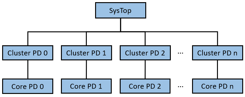
To identify a power-down request, SCP analyses the SCMI message received from AP. The power-down process is executed in a bottom-to-top manner within the power tree. Starting from the bottom, SCP powers down the power domains sequentially (The current power domain HAL is simply returning success, this need to be updated to program the PPU registers).
Upon completing the power-down of power domains, SCP signals the RSE using the same SCMI message format received from AP. This prompts RSE to execute its shutdown sequence. Subsequently, SCP notifies the MCP with the identical SCMI messaging format.
Upon receiving the shutdown request, MCP initiates the power-down sequence and outputs the shutdown message to the UART console. This message serves as the trigger for the FVP to terminate its execution.
Cold reboot
The cold reboot flow mirrors the shutdown process until the communication with the RSE and MCP stages. In the case of a cold reboot, SCP alters the sequence by informing MCP before RSE.
Upon receiving the cold reboot message, MCP initiates its power-down sequence and enters WFI mode. RSE executes its power-down sequence and triggers a system-wide reset by programming the system reset register. This action induces a complete system reboot.
Warm reboot
During a warm reboot, the System Control Processor (SCP) undertakes the following steps:
SCP programs the Power Processing Units (PPUs) for all CPUs to transition into a static OFF state, while leaving the cluster PPUs untouched.
SCP then awaits the transition of all CPUs into the static OFF state.
After confirming that all cores have entered static OFF, SCP proceeds to power up the boot CPU.
The boot CPU starts from the BL1 stage, initiating the warm reboot process.
Download and build the required platform software
For downloading and building the platform firmware, refer Busybox Boot.
Validating Shutdown/Reboot
Shutdown
To verify the shutdown functionality, boot the platform to busybox. From busybox command line, issue the command
poweroff -f
Cold reboot
To verify the cold reboot functionality, boot the platform to busybox. From busybox command line, issue the command
reboot -f
Warm reboot
To verify the warm reboot functionality, boot the platform to Grub. Press the key ‘e’ to edit command line and append ‘reboot=warm’. The resulting command line will appear as follows:
linux /Image acpi=force ip=dhcp root=PARTUUID=9c53a91b-e182-4ff1-aeac-6ee2c432ae94 rootwait verbose debug reboot=warm
After making the edit, proceed with the boot by pressing the ‘F10’ key and allow the platform to boot into busybox. Once at the busybox command line, issue the following command:
reboot -f