System Monitoring Control Framework (SMCF)
Important
This feature might not be applicable to all Platforms. Please check individual Platform pages, section Supported Features to confirm if this feature is listed as supported.
Overview of SMCF
The System Monitoring Control Framework is designed to manage a large and diverse set of on-chip sensors and monitors. It does this by presenting software with a standard interface to control the monitors, regardless of type, and reducing software load of controlling the monitor sampling and data collection.
The SMCF reduces the burden on monitor control by enabling sampling on multiple monitors to be controlled together and by various triggers either internal or external to the SMCF. The number of monitors that the SMCF supports can be configured. The SMCF eases data collection requirements by allowing the data from multiple monitors to be collated in a single location or writing out data to a memory-mapped location that is easier for the monitoring agent to access.
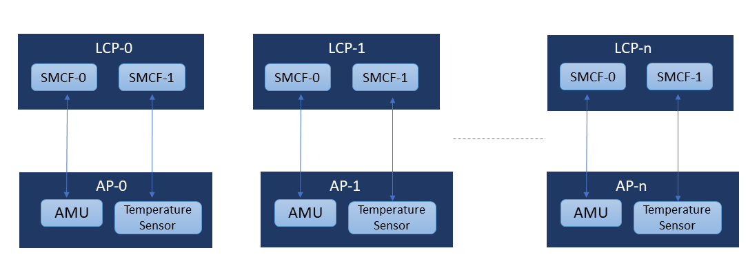
SMCF can effectively manage sensors, track activity counters, and monitor dynamically evolving system data. The SMCF consists of two components, an MGI and an MLI.Each data source is called a monitor and connects to an MLI (Monitor Local Interface).The data width of each monitor could be anything from one bit to 64bits.Each group of MLI’s is connected to one MGI (Monitor Group Interface),which provides the software interface and a set of functions to be applied to a group of monitors. SMCF MGIs (and related MLIs) are implemented in the LCP subsystem for core temperature sensors and AMU. The diagram below shows the SMCF internal view with LCP and AP:
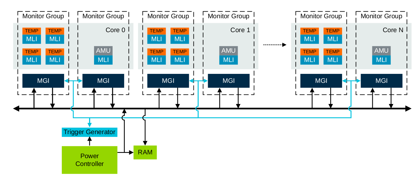
There is a trigger input from the SCP, this is used to trigger a sample on the SMCF MGI. This allows the SCP to trigger a simultaneous sample on all relevant sensors and monitors.The single trigger input to the LCP is connected to all the MGI input triggers in the LCP. The diagram below gives the simplified SoC structure of SMCF:
There are four modes to sampling the data:
Manual Trigger : Initiated by the software for a single sample from the SMCF.
Periodic Sample: Software-driven continuous sampling at predefined interval.
Data Read: Data read sampling is used when a sample is required to be started when the data from the previous monitor sample data set is consumed. When the last data value from a monitor sample data set is read, a new sample begins.
Input Trigger: External event initiated sampling. Input trigger sampling is used when a sample is required to be started from an event that is external to an MGI.
SMCF Software Flow and Configuration
SCP accesses the SMCF Region through cluster utility mmap, which is mapped to the SCP address translation window.
The single trigger input to the LCP is connected to all the MGI input triggers in the LCP.Each MGI can be configured to start a sample based on this input trigger.
Software configures the MGI register base address,sample type, MGI write address,SMCF SRAM read address and respective IRQs.
Software is expected to write to this SMCF MGI Trigger enable register on a regular interval of time to initiate the sensor data collection. The trigger output from this register is expected to go to all MGIs.
The SMCF framework collect the data from MGI and update the SMCF SRAM on receiving the trigger. Software reads the sensor data from the SMCF SRAM.
Any platform with SMCF uses the SMCF to read out the AMU data instead of directly accessing the AMU data.
SMCF client module uses AMU smcf and platform smcf module for AMU data collection and for using the data sampling APIs.
The platform smcf module exposes platform specific data sampling APIs i.e start and stop sampling.
SMCF client module in SCP binds to AMU SMCF module to read out the AMU data, currently only the ARCH counters are being read.
SMCF client, on receiving instructions from the user, triggers the sampling and gives out AMU data as output in the console.
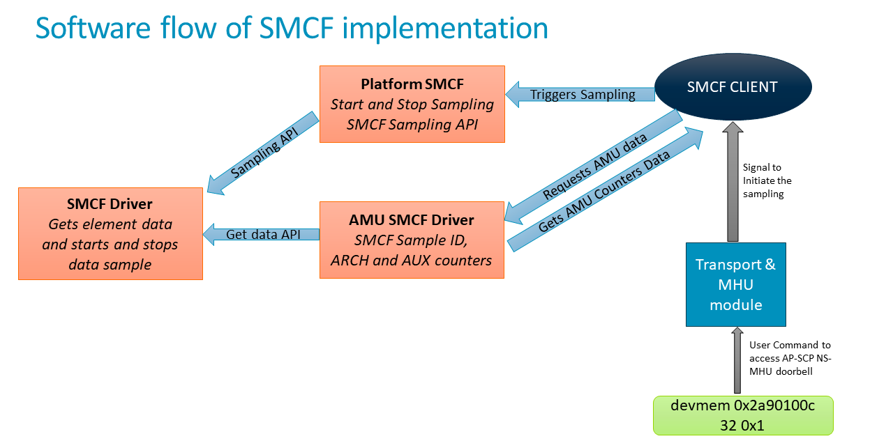
SMCF client is controlled by AP-SCP Non-secure MHU channel. SMCF client binds to Transport module for receiving MHU signal. User from AP Linux console rings AP-SCP Non-secure MHU channel doorbell. On receiving MHU interrupt MHU module through Transport module will signal SMCF client module to start, capture and stop SMCF sampling.
The diagram below explains the software flow of SMCF:
Download and build the required platform software
For downloading and building the platform firmware, refer Busybox Boot or Buildroot boot documentation.
Validating the SMCF
From the user end, start the SMCF sampling by following procedure:
Executing devmem command from Linux console for accessing AP-SCP NS-MHU doorbell channel.
devmem 0x2a90100c 32 0x1
This will launch the SMCF sampling and prints the collected sample data in the SCP console. The output will show 3 AMU counter values for all cores present in platform. For RD-V3-Cfg1 platform 8 such instances will be there. An example output looks like below:
[SMCF_CLIENT] Data successfully fetched for MGI[0]
[SMCF_CLIENT] MGI[0] AMU_COUNTER[0] data = 5077165163
[SMCF_CLIENT] MGI[0] AMU_COUNTER[1] data = 175172523
[SMCF_CLIENT] MGI[0] AMU_COUNTER[2] data = 5077165163
[SMCF_CLIENT] MGI[0] AMU_COUNTER[3] data = 0
[SMCF_CLIENT] MGI[0] AMU_COUNTER[4] data = 0
[SMCF_CLIENT] MGI[0] AMU_COUNTER[5] data = 0
[SMCF_CLIENT] MGI[0] AMU_COUNTER[6] data = 0
[SMCF_CLIENT] Data successfully fetched for MGI[1]
[SMCF_CLIENT] MGI[1] AMU_COUNTER[0] data = 3201246
[SMCF_CLIENT] MGI[1] AMU_COUNTER[1] data = 110394
[SMCF_CLIENT] MGI[1] AMU_COUNTER[2] data = 3201246
[SMCF_CLIENT] MGI[1] AMU_COUNTER[3] data = 0
[SMCF_CLIENT] MGI[1] AMU_COUNTER[4] data = 0
[SMCF_CLIENT] MGI[1] AMU_COUNTER[5] data = 0
[SMCF_CLIENT] MGI[1] AMU_COUNTER[6] data = 0
Optional Changes for FVP based platforms
For getting precise readings on FVP, please use the parameters below: 1. Export these variables before launching the model:
export FASTSIM_DISABLE_TA=0
Pass
--quantum=400as model parameter and pass--min-sync-latency=1also as model parameter.