Boot Flow for RD-Fremont Multi Chip Variants
Overview
This section describes the software boot process for the following platforms:
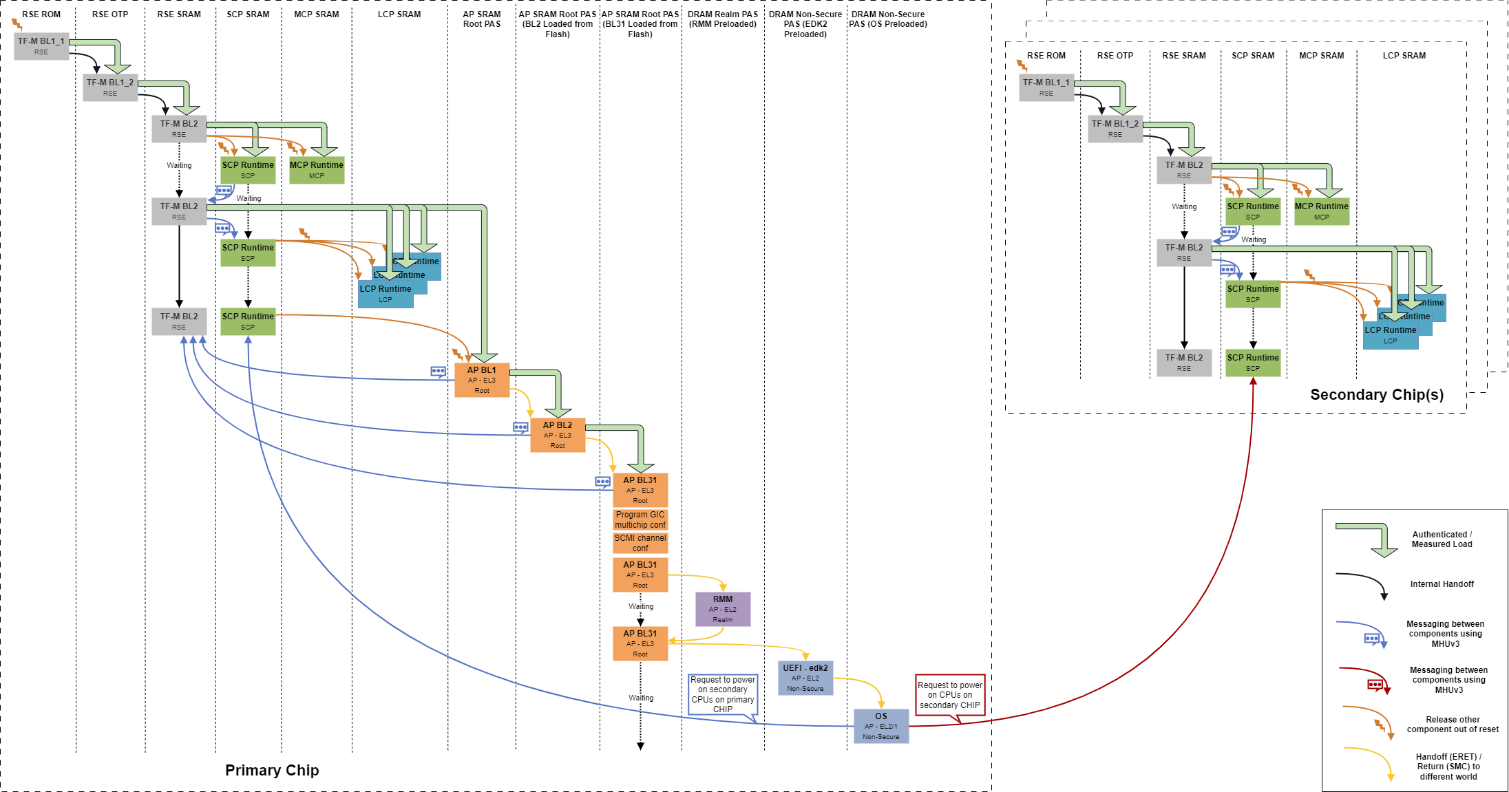
A simplified boot flow diagram is shown below.
Subsystem Roles
Runtime Security Engine
On platform reset, RSE on each chip are released out of reset and SCP and MCP are held in reset state. RSE on each chip begin executing the TF-M’s BL1_1 from RSE ROM and provision the BL1_2 image into the One Time Programmable flash (OTP) of the respective chip and transfers the execution to the BL1_2 stage. More details on the provisioning can be found in the TF-M’s RSE provisioning page. BL1_2 authenticates and loads the TF-M’s BL2 (MCUBoot) stage which is responsible for authenticated loading of the next stage images as well as images of the other components in the respective chip. More details on BL2 can be found in Image Loading Using MCUBoot page. BL2 stage is also responsible for setting up the SCP’s ATU, NI-Tower instances and releasing SCP and MCP out of reset.
System Control Processor
SCP is responsible for managing the per chip system power, setting up of the interconnect and configuring the interconnect for cross chip communication. More details on the interconnect setup can be found in CMN Cyprus Driver Module and in - CMN Cyprus Multichip Configuration page. SCP is also responsible for releasing the LCPs out of reset after RSE loads the LCP firmware into ITCMs. RSE has to wait for the SCP to turn on the SYSTOP power domain before loading the LCP images. To maintain this synchronization, SCP and RSE communicates messages through MHUv3. More details on this can be found in SCP-RSE Communication page. Only the SCP on the primary chip releases the primary core out of reset. At this point, SCP on the secondary chips will wait for the SCMI messages.
Local Control Processor
LCP is responsible for managing per Application Processor’s power. The boot sequence of LCP is summarized in Local Control Processor page.