Boot Flow for RD-Fremont Single Chip Variants
Overview
This section describes the software boot process for the following platforms:
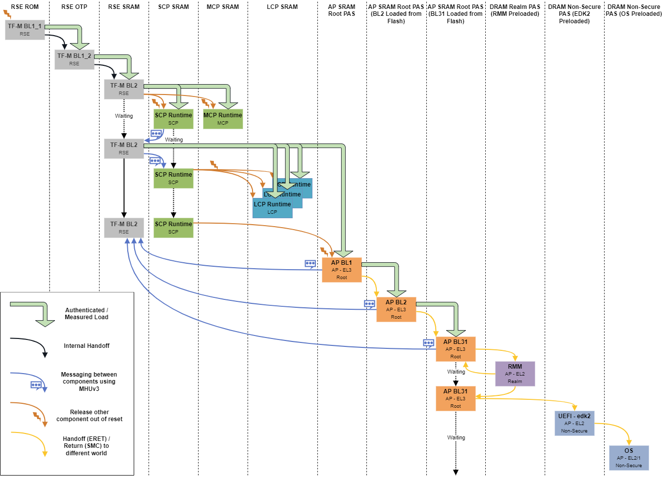
A simplified boot flow diagram is shown below.
Subsystem Roles
Runtime Security Engine
On platform reset, RSE is released out of reset and SCP and MCP are held in reset state. RSE begin executing the TF-M’s BL1_1 from RSE ROM and provision the BL1_2 image into the One Time Programmable flash (OTP) and transfers the execution to the BL1_2 stage. More details on the provisioning can be found in the TF-M’s RSE provisioning page. BL1_2 authenticates and loads the TF-M’s BL2 (MCUBoot) stage which is responsible for authenticated loading of the next stage images as well as images of the other components. More details on BL2 can be found in Image Loading Using MCUBoot page. BL2 stage is also responsible for setting up the SCP’s ATU and releasing SCP and MCP out of reset.
System Control Processor
SCP is responsible for managing the system power and setting up of the interconnect. More details on the interconnect setup can be found in CMN Cyprus Driver Module page. SCP is also responsible for releasing the LCPs out of reset after RSE loads the LCP firmware into ITCMs. RSE has to wait for the SCP to turn on the SYSTOP power domain before loading the LCP images. To maintain this synchronization, SCP and RSE communicates messages through MHUv3. More details on this can be found in SCP-RSE Communication page.
Local Control Processor
LCP is responsible for managing per Application Processor’s power. The boot sequence of LCP is summarized in Local Control Processor page.
Application Processor
Application Processor (AP) is responsible for hosting the user’s software stack. Trusted Firmware (TF-A) is executed at boot time to setup the root monitor, which executes at root EL3 mode. User’s software stack includes a host hypervisor hosted at Non-Secure EL2 mode, a Realm Management Monitor (TF-RMM) deployed at Realm EL2 mode, guest virtual machine spawned in Realm/Non-secure EL1 and host/guest userspace applications running at Realm/Non-secure EL0.
In RD-Fremont platform, TF-M BL2 (MCUBoot) stage authenticates and loads TF-A BL1 image binary into AP SRAM. When SCP releases AP out of reset, AP starts with TF-A BL1 stage, following which TF-A BL1 authenticates and loads TF-A BL2 and passes the control to it. Furthermore TF-A BL2 follows same process to load the next stage TF-A BL31. TF-A BL31 is the runtime root monitor which sets up the TF-RMM interface and triggers the RMM initialization. TF-RMM communicates with TF-A BL31 on few occasions during its init. Once TF-RMM returns control back, TF-A BL31 hands off the control to Non-Secure BL33 image which is UEFI in current implementation which then take care of host OS/hypervisor boot. At each stage of authenticated loading of image, measurements of the loaded image is computed and extended to RSE, that is later used to produce delegated attestation key and token required by TF-RMM. More detailed info can be found here in AP-RSE Attestation Service.